
Download:
Share Link:http://lixin.fun/cloud/index.php?share/folder&user=1&sid=2e84Csxc Password:JIpom
To run Atomsk, go to the Windows menu, click Accessories, and open Windows® Power Shell. Once in the shell, you can run Atomsk by entering its full path, and your arguments. e.g.
& "C:\Program Files (x86)\Atomsk\atomsk.exe" --create fcc 4.02 Al aluminium.xsf
- Basics: the example of the symmetric tilt grain boundary
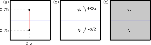
Tilt grain boundaries are a specific type of grain boundary, where the two grains are rotated around the same crystallographic axis. When the two grains are rotated by opposite angles, the tilt grain boundary is symmetric. The steps to construct a symmetric tilt grain boundary are as follow (here we consider the Cartesian Y axis as being normal to the grain boundary, and Z normal to the figure):
- Constructing a grain boundary in aluminium
atomsk --create fcc 4.046 Al aluminium.xsf
"atomsk" is & "C:\Program Files (x86)\Atomsk\atomsk.exe" As an example, let us construct a {210}[001] symmetric grain boundary in aluminium. We want the two grains to meet with {210} surfaces, so we need to turn the crystals by ±26.57° around the Z axis. Create a new text file and copy the following information inside:
box 100 100 0
node 0.5box 0.25box 0 0° 0° -26.57°
node 0.5box 0.75box 0 0° 0° 26.57polyX.txt
This file has to comply to the format expected in the mode "--polycrystal", as explained in the previous tutorial. A grain boundary is just a special case of a polycrystal where only two grains are constructed -each keyword "node" corresponds to one grain. The first grain is located at the position (0.5,0.25,0) and the second one at (0.5,0.75,0) as explained above. The first grain is rotated by 0° around X, 0° around Y, and -26.57° around the Z axis; similarly the second grain is only rotated by +26.57° around the Z axis. Also, note that in the first line the dimension of the box is set to zero along the Z direction. Atomsk will automatically replace that zero with the size of the seed along Z -in that case, by the lattice parameter of the aluminium unit cell, 4.046 Å. Now, all one has to do is run Atomsk in mode "--polycrystal", using the file "aluminium.xsf" as a seed, and the parameters from the file "polyX.txt":
atomsk --polycrystal aluminium.xsf polyX.txt polycrystal.cfg
- Dealing with boundary conditions
The instructions above construct two grains with the desired orientation, however the visualization (e.g. with Atomeye) shows that there are problems at the boundaries of the cell. Indeed, in the parameter file "polyX.txt" the size of the box was arbitrarily set to 100 Å along X and Y, which does not match the periodicity of the lattice. Along the X and Y Cartesian axes are <210> directions of the crystal. Along these directions the periodicity of the lattice is 4.046*√5, therefore the dimensions of the box must be an integer number of that value to ensure periodicity. For instance:
box 9.047131 36.188524 0
node 0.5box 0.25box 0 0° 0° -26.57°
node 0.5box 0.75box 0 0° 0° 26.57°polyX.txt
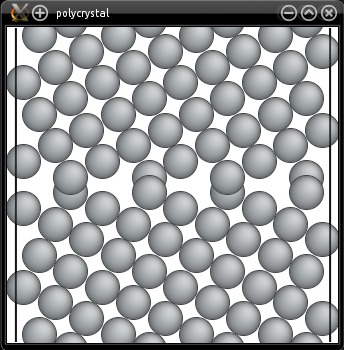
Constructing the polycrystal with this file instead of the previous one should yield a proper tilt grain boundary, with periodic boundary conditions. Also, because of periodicity there are grain boundaries at the top and bottom of the cell. Using appropriate box dimensions ensures that these grain boundaries are strictly equivalent to the one at the center of the cell. Here we chose different box lengths along X and Y, but we could have used identical values. You can play with these values to construct smaller or larger systems while still keeping periodicity. You may open the final system "polycrystal.cfg" with Atomeye for visualization:
- Other types of grain boundaries
Comments